How to Install a Surge Protection Device — UK Installer Guide
How to Install a Surge Protection Device — UK Installer Guide
An SPD is only as effective as its installation. A 40kA device installed with 2-metre cable leads can perform no better than a 5kA device installed correctly. The physics are straightforward: surge energy travels as a high-frequency voltage transient, and any inductance in the connection cable — proportional to its length — reduces the device's ability to clamp the surge before it reaches connected equipment. This guide covers correct installation practice for Type 2 SPDs in UK consumer units and distribution boards.
The golden rule: keep connection cables short
The total cable length from the SPD's live connection point to the SPD terminals, plus from the SPD earth terminal to the main earth bar, should be kept as short as possible — ideally under 0.5m in total, and never more than 1m combined. Every 0.5m of additional cable adds approximately 0.5–1µH of inductance, which translates directly into reduced surge clamping performance.
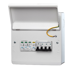
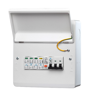
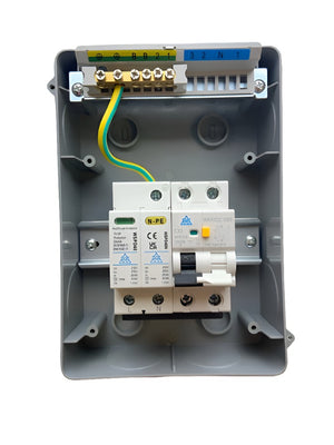
This is why SPDs installed inside the consumer unit — connected directly to the busbar and earth bar — outperform remote devices connected via longer cable runs. The WCED WSPDT2-CB includes a pre-fitted cable set sized for standard consumer unit installation to make correct cable length straightforward.
Step-by-step installation — Type 2 SPD in consumer unit
| Step | Action | Notes |
|---|---|---|
| 1 | Isolate the consumer unit — main switch off, prove dead | Notifiable work — competent person only |
| 2 | Identify the SPD installation position on the DIN rail | Ideally adjacent to or near the main switch |
| 3 | Connect SPD live terminal to the busbar or main switch output | Keep connection cable under 0.5m — use pre-fitted cable if supplied |
| 4 | Connect SPD neutral terminal to the neutral bar | 2-pole SPD only — 4-pole also requires L2, L3 connections |
| 5 | Connect SPD earth terminal directly to the main earth bar | Direct connection — do not share with other earth conductors if avoidable |
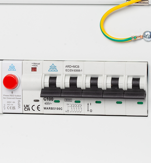
| 6 | Fit the overcurrent protective device (OCPD) on the SPD supply side | Typically 63A fuse or MCB — check manufacturer specification |
| 7 | Verify the SPD status indicator is green before restoring supply | Red or absent indicator means SPD element has failed |
| 8 | Restore supply and test — record on installation certificate | SPD installation should be noted on the EICR/installation certificate |
Earthing arrangements
The SPD earth connection must be made to the main protective earth (PE) bar — not a circuit earth terminal or CPC. On TN-C-S (PME) systems, this is the combined neutral/earth bar at the consumer unit. On TT systems, the earth bar connected to the installation earth electrode. The earth connection must be as short and direct as possible — this is the most critical connection in the installation.
Common installation mistakes
The WSPDT2-CB includes a pre-fitted cable set for correct installation length. Type 2 40kA. In stock.
View SPD range →Frequently Asked Questions
Does an SPD need its own MCB?
Yes — a dedicated overcurrent protective device (OCPD) should be installed on the supply side of the SPD. This protects the SPD supply cable in the event of an SPD failure mode and is specified by most manufacturers. A 63A MCB or fuse is typically used. Some SPD models include a built-in disconnector or fuse — check the manufacturer's datasheet.
What does the SPD status indicator show?
Most modern SPDs include a green/red status indicator window. Green means the SPD's protective element (typically a Metal Oxide Varistor) is intact and functional. Red means the protective element has been exhausted by a surge event and the device no longer provides protection — it should be replaced. Some models also include a remote signal contact for building management system integration.
Where should the SPD appear on the installation certificate?
The presence and location of any SPD should be recorded on the Electrical Installation Certificate (EIC) or Minor Works Certificate as appropriate. The risk assessment for surge protection should also be documented — either confirming that an SPD has been installed, or recording the reasons why one was not required following the risk assessment.
Electrical Safety Knowledge Base
All guides covering protection devices, surge protection, and enclosures for UK installers.
-
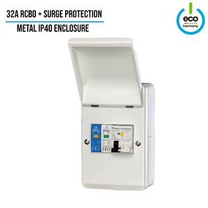
RCBO + Surge Protection – Fitted Consumer Unit IP40 – 3 Phase
Regular price From £69.00Regular price -

3-Phase PME PEN Fault Protection – 40A RCBO + Surge | Single EV Charger | BS7671 Compliant
Regular price From £80.00Regular price -
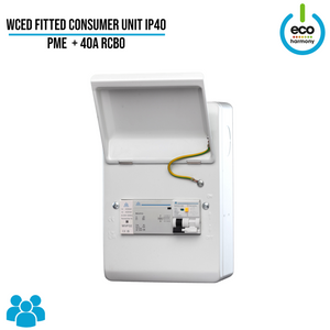
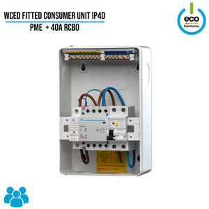
Fitted Consumer Unit IP40 – PME + 40A RCBO (Surge Protection + kWh Meter + Load Balancing Options Available)
Regular price From £85.00Regular price -
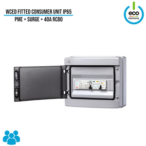
Fitted Consumer Unit IP65 - PME + 40A RCBO + Surge Protection
Regular price From £82.50Regular price -
Save £2.50
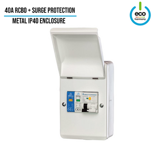
RCBO + Surge Protection Fitted Consumer Unit (IP30 / Indoor Use)
Regular price £32.50Regular price£35.00-£2.50 Sale price £32.50 -
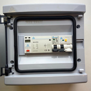
IP65 Consumer Unit with RCBO + Type 2 Surge Protection
Regular price £33.50Regular price£26.00Sale price £33.50


-


Simpson & Partners Cable Hook – Keep Your Charger Tidy & Stylish
Regular price £60.00Regular price -


Home Series 7kW Plus EV Charger – Type 2 Socket
Regular price From £615.00Regular price -


Home Series 7 kW Plus Home EV Charger, Type 2 Tethered
Regular price From £715.00Regular price -


Home Series 7kW Basic EV Charger – Type 2 Socket
Regular price £510.00Regular price -


Free Colour Sample Card – Simpson & Partners EV Chargers
Regular price £0.00Regular price


