

Many installers treat RCBOs as a straightforward box-tick, yet the reality is far more demanding. In UK EV charging installations, RCBOs are a legal and safety cornerstone, not an optional upgrade. Get the selection or termination wrong, and you risk compromised tripping, failed inspections, and real danger to end users. This guide cuts through the confusion, covering RCBO function, UK regulatory requirements including BS 7671 and the IET Code of Practice, PME protection obligations, and practical integration advice that experienced installers can apply immediately on site.
Table of Contents
- Understanding RCBOs: Role and function in EV charging
- Regulations and standards: BS 7671, IET Code of Practice, and PME protection
- Choosing the right RCBO for EV charging: Types, features, and selection criteria
- Integrating RCBOs with EV chargers: PME protection, best practice, and quality assurance
- What most guides miss: The real impact of RCBO choice and PME integration
- Explore quality RCBOs and PME solutions for EV charging
- Frequently asked questions
Key Takeaways
| Point | Details |
|---|---|
| Dual protection | RCBOs combine earth leakage and overcurrent protection, essential for EV charging safety. |
| Compliance first | BS 7671 and IET CoP require RCBOs and PME protection for UK EV charger installations. |
| Correct FE lead | Always terminate the Functional Earth (FE) lead directly to the earth bar for RCBO reliability. |
| Choose wisely | Select RCBO types with DC sensitivity to match EV charger requirements and avoid installation mistakes. |
| Test with simulators | Post-installation RCBO testing using vehicle simulators ensures full compliance and safety. |
Understanding RCBOs: Role and function in EV charging
The term RCBO stands for Residual Current Circuit Breaker with Overcurrent protection. It is a single device that combines two distinct protective functions into one unit. The first is residual current detection, which monitors for earth leakage faults. The second is overcurrent protection, which guards against excessive current that could damage cables or cause fires. In a standard domestic consumer unit, these functions might be split across separate devices. In EV charging installations, combining them in a single RCBO is both practical and, in many cases, required.
Why does EV charging demand this level of protection? EV chargers draw sustained high currents, often at 32A for a 7.4kW single-phase unit. That sustained load creates conditions where both earth leakage and overcurrent faults are more likely than in typical household circuits. Add to this the sensitivity of PME (Protective Multiple Earthing) systems, and the need for a reliable, correctly specified RCBO becomes clear.
Here is a summary of the core functions an RCBO performs in an EV charging circuit:
- Earth leakage detection: Trips the circuit when it detects a residual current above the rated threshold, typically 30mA for personal protection.
- Overcurrent protection: Disconnects the circuit when current exceeds the rated value, protecting cables and connected equipment.
- Single-pole plus neutral switching: Ensures both live and neutral conductors are isolated on fault, which is critical for safety.
- DC fault sensitivity (in Type A and above): Detects pulsating DC faults generated by EV charger electronics, which standard RCDs cannot detect.
One detail that many installation guides overlook is the Functional Earth (FE) lead. This small lead, present on many modern RCBOs, must be connected directly and securely to the earth bar. According to proper FE lead termination, clipping or leaving this lead loose compromises the RCBO’s ability to trip correctly when neutral is lost. This is not a minor detail. In a PME installation, a lost neutral scenario is precisely the condition where correct tripping is most critical.
Key principle: An RCBO is only as effective as its installation. Correct FE lead termination is not optional; it is the difference between a device that works and one that fails when it matters most.
When selecting RCBOs for EV installations, you have several product options to consider. Type A RCBOs are the standard choice for most domestic EV charger circuits. For installations requiring sensitivity to smooth DC faults, DC-sensitive RCBOs provide an additional layer of protection. The CHINT RCBO range offers a reliable, cost-effective option for installers who need proven performance at scale.

Regulations and standards: BS 7671, IET Code of Practice, and PME protection
Understanding the function of RCBOs sets the stage for compliance, so let’s detail the regulations and standards that guide installation and protection.
The primary wiring regulation in the UK is BS 7671+A2:2022, also known as the 18th Edition with Amendment 2. Section 722 of BS 7671 deals specifically with electric vehicle charging installations. It sets out requirements for protective devices, earthing arrangements, and circuit design. Compliance with BS 7671 is not advisory; it is the legal baseline for all electrical installation work in the UK.
Alongside BS 7671, the IET Code of Practice for Electric Vehicle Charging Equipment Installation (5th Edition) provides detailed, EV-specific guidance. The 5th Edition IET CoP emphasises full BS 7671+A2:2022 alignment, addresses Vehicle-to-Grid (V2G) technology, fire safety requirements under RC59, and importantly, now expects testing with vehicle simulators rather than relying solely on standard test equipment.
PME protection deserves particular attention. In a PME system, the neutral and earth conductors are combined at the supply point. This arrangement is common across the UK and is generally safe for fixed wiring. However, when an EV charger is connected to a PME system, a broken or lost neutral can cause the vehicle’s chassis to rise to a dangerous potential relative to true earth. This is why BS 7671 Section 722 requires specific protective measures, including the use of a PEN fault detection device or an appropriate earthing arrangement, when connecting EV chargers to PME supplies.
| Regulation or standard | Scope | Key requirement for EV charging |
|---|---|---|
| BS 7671+A2:2022 Section 722 | Mandatory wiring regulation | Protective devices, earthing, circuit design |
| IET CoP 5th Edition | EV-specific best practice | PME protection, V2G, vehicle simulator testing |
| OZEV/LEVI regulations | Grant-funded installations | Smart charging, data reporting |
| RC59 | Fire safety | Charger installation in fire-risk locations |
A practical note on PME compliance: simply fitting an RCBO is not sufficient on its own. You must also assess whether the installation requires a PEN fault detection device. For many domestic installs on a TN-C-S (PME) supply, this is now an expected part of the design. RCBO consumer units that are pre-fitted with surge protection and designed for EV applications simplify this process considerably, reducing the risk of errors during installation.
Vehicle simulator testing is another area where the standards have moved forward. Previously, installers might use a standard loop impedance tester and RCD tester to verify protection. The IET CoP 5th Edition now expects that testing reflects the actual conditions of EV charging, including the DC components generated by charger electronics. Vehicle simulators replicate these conditions, giving you confidence that your RCBO will perform correctly in real-world use.
Choosing the right RCBO for EV charging: Types, features, and selection criteria
With regulatory context established, installers need to know how to choose the right RCBO. Let’s break down types, features, and selection criteria.
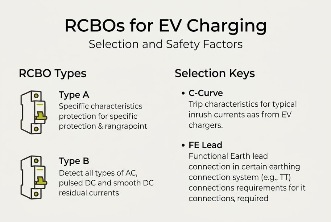
The most important distinction when choosing an RCBO for EV charging is the type of RCD sensitivity. This determines which fault currents the device can detect and respond to.
| RCBO type | Detects | Typical EV application |
|---|---|---|
| Type AC | Sinusoidal AC faults only | Not suitable for EV charging |
| Type A | AC and pulsating DC faults | Standard domestic EV charger circuits |
| Type B | AC, pulsating DC, and smooth DC | Three-phase chargers, higher-power installs |
| Type F | AC, pulsating DC, and frequency-variable | Some modern inverter-driven chargers |
For the majority of domestic EV charger installations using a single-phase 7.4kW charger, a Type A RCBO rated at 30mA is the correct starting point. Type A devices detect the pulsating DC faults that EV charger electronics produce, which Type AC devices cannot. Using a Type AC RCBO in an EV charging circuit is a non-compliant choice that could leave the installation vulnerable to undetected faults.
Here is a step-by-step selection process you can follow for each installation:
- Confirm the supply type: TN-C-S (PME), TN-S, or TT. This affects earthing design and PME protection requirements.
- Determine the charger output: Single-phase 7.4kW requires a 32A circuit; three-phase 22kW requires a 32A three-phase circuit.
- Select RCBO type: Type A for most domestic installs; Type B for three-phase or higher-power commercial chargers.
- Check the curve type: C-curve RCBOs are standard for EV charger circuits, providing tolerance against the inrush current at charger startup.
- Verify voltage and current rating: Ensure the RCBO matches the circuit voltage (230V single-phase or 400V three-phase) and the design current.
- Confirm FE lead requirements: Check the manufacturer’s instructions for FE lead termination and ensure your consumer unit has a suitable earth bar connection point.
A 32A RCBO with Type A sensitivity and C-curve is the most common specification for a 7.4kW domestic EV charger. For installations requiring weatherproof enclosures, weatherproof RCBO units rated to IP65 provide the necessary protection for outdoor or exposed locations.
Pro Tip: Always check whether the EV charger manufacturer specifies a minimum RCBO type in their installation manual. Some charger brands require Type B or even Type F devices. Installing a Type A RCBO where Type B is required will void the charger warranty and may result in a non-compliant installation.
Common mistakes to avoid include fitting a Type AC RCBO (not suitable for EV use), ignoring the FE lead termination requirement, selecting an RCBO with a B-curve instead of C-curve (which may cause nuisance tripping on startup), and using an undersized earth bar that cannot accommodate the FE lead alongside other protective conductors. An RCBO surge protection pack that combines RCBO protection with a surge protection device (SPD) in a single pre-fitted unit reduces the chance of these errors occurring.
Integrating RCBOs with EV chargers: PME protection, best practice, and quality assurance
Selecting the right RCBO is half the job. Next, discover how to integrate RCBOs for PME protection and compliance with UK best practice.
Effective integration means thinking beyond the RCBO in isolation. A compliant EV charging installation on a PME supply requires a layered approach to protection. That means combining your RCBO with a PEN fault detection device, a surge protection device (SPD), and a quality charger that supports smart tariff and solar compatibility where required.
Key integration steps and best practice points include:
- PEN fault detection: On TN-C-S (PME) supplies, fit a PEN fault detection device upstream of the EV charger circuit. This device monitors for a broken PEN conductor and disconnects the charger before dangerous voltages can appear on the vehicle chassis.
- Surge protection device (SPD): Fit an SPD at the consumer unit to protect charger electronics from transient overvoltages. This is now a recommended practice under BS 7671+A2:2022 and is particularly important for smart chargers with communication modules.
- Earth bar integrity: Ensure your consumer unit’s earth bar is rated to accept all protective conductors, including the RCBO FE lead. A crowded or undersized earth bar is a common source of installation defects.
- Cable sizing and routing: EV charger circuits must be sized for continuous loading (typically 32A for 7.4kW), not just the design current. Route cables to avoid thermal derating from bundling or thermal insulation.
- Post-installation testing: Test the RCBO tripping function using a vehicle simulator, as vehicle simulator testing is now emphasised in the IET CoP 5th Edition. Standard RCD testers do not replicate the DC components present in EV charging circuits.
A 3-phase RCBO consumer unit pre-fitted with surge protection is an efficient solution for commercial or three-phase domestic installations, reducing installation time and the risk of wiring errors. For single-phase installs where a lower output is appropriate, a 16A RCBO may be specified for Mode 2 or lower-rated charger circuits.
Pro Tip: Document every protection device fitted, including make, model, type, and the FE lead termination method used. This documentation supports your Electrical Installation Certificate and provides evidence of compliance if the installation is ever inspected or queried by a DNO (Distribution Network Operator).
Quality assurance does not end at commissioning. Advise your customers to have the installation inspected periodically, particularly if the property changes ownership or the charger is upgraded. RCBO tripping characteristics can degrade over time, especially in environments with high levels of electrical noise or frequent fault conditions.
What most guides miss: The real impact of RCBO choice and PME integration
Most installation guides cover the regulatory requirements clearly enough. What they rarely address is the gap between a technically compliant installation and one that will genuinely protect people and property over the long term.
The FE lead issue is a prime example. We see installations where the FE lead has been clipped back or left unconnected because the installer was not aware of its function. The FE lead termination requirement is not buried in obscure guidance; it is a fundamental part of how the RCBO operates in a lost-neutral scenario. Yet it is routinely missed in quick-turnaround installs where the pressure to complete jobs fast overrides careful practice.
The same applies to PME protection. Many installers treat PEN fault detection as a regulatory tickbox rather than a genuine safety measure. The reality is that a PEN fault on a domestic supply is rare but catastrophic when it occurs. Layered protection, combining a PEN fault device with a correctly specified and terminated RCBO, is what separates a safe installation from one that merely passes an initial inspection.
Our practical advice: always test RCBO tripping with a vehicle simulator, not just a standard RCD tester. The difference in test results can reveal faults that would otherwise go undetected until a real fault condition arises.
Explore quality RCBOs and PME solutions for EV charging
If this guide has clarified your approach to RCBO selection and PME integration, the next step is sourcing the right components for your installations.

At EcoHarmony, we supply RCBOs, PME RCBO consumer units, surge protection packs, and premium EV chargers designed for compliant UK installations. Our range includes products pre-configured for EV charging circuits, reducing installation time and minimising the risk of specification errors. Whether you need a 22kW EV charge point for a commercial site or a complete domestic protection board, you will find installer-ready solutions at EcoHarmony. Every product we stock is selected to meet BS 7671 and IET Code of Practice requirements, supporting safe and reliable installations every time.
Frequently asked questions
Do RCBOs provide both earth leakage and overcurrent protection in EV circuits?
Yes, RCBOs combine both residual current detection and overcurrent protection in a single device, making them the preferred choice for EV charging circuits where both fault types are a real risk.
What is the importance of PME protection when installing EV chargers?
PME protection is required by UK regulations to prevent dangerous voltages appearing on a vehicle chassis if the PEN conductor is lost, which is a specific hazard in TN-C-S supply systems.
Why must the Functional Earth (FE) lead be connected directly to the earth bar in RCBOs?
Clipping the FE lead or leaving it unconnected prevents the RCBO from tripping correctly under lost-neutral conditions, which is precisely when reliable tripping is most critical in a PME installation.
Are vehicle simulators required for RCBO testing in EV charger installations?
Vehicle simulators are now expected under the IET Code of Practice 5th Edition to verify that RCBO protection functions correctly under the actual DC fault conditions produced by EV charger electronics.